
Preserving the Sound of Your Vintage Audio Equipment
Restoring Classic Audio Gear to Their Original Glory
Restoring the Heart of Classic Audio Systems
Read the Article below for an interesting insight on the repair of Hi-Fi Equipment and the setting up of a workshop.
If the thought of attempting to repair your own vintage audio equipment seems a little daunting, please scroll down further to see the repair service I can offer!
Tim Jarman on the tools and techniques you’ll need to restore classic kit
In the early days of hi-fi it was common to make one’s own equipment, either as an economy measure or as a matter of pride. Today’s equivalent may be repairing and restoring vintage hi-fi units at home, a potentially rewarding endeavour which can make the subsequent listening even more satisfying.
The ability to repair hi-fi kit to the highest standard is one of those 10,000 hour skills that takes commitment to master, but it is surprising what can be done with just a little patience and study.
Avoiding Mistakes
A basic grounding in electronics will be required, such as the ability to read a circuit diagram and an appreciation of what the various types of component do. You’ll also need a full understanding of the potential dangers of mains-powered equipment and how to use your tools safely and effectively. There are simply no shortcuts in this preparation and you will get nowhere without it.
The next step is to choose what you are going to practice on. Don’t make your first mistakes on equipment that is valuable, either in sentimental or financial terms. The world is full of broken hi-fi kit and there’s plenty to hone your skills on.
In choosing what to buy (or allow yourself to be given, because a lot of this stuff is free) I would recommend starting with Japanese and Continental components from the mid ’70s to the mid ’80s. It is ubiquitous, generally safe and solid, free of designed-in faults and quirks and normally has comprehensive service data available for it.
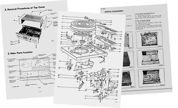
A library of service sheets used to be jealously guarded by any workshop that had the resources to amass it, but now full manuals can be downloaded from a number of sources, usually free of charge.
Condition is another factor to consider. Mint examples would be an extravagance at this stage, but it is worth seeking out pieces that are at least complete and not obviously the result of someone else’s failed repair or upgrade attempts.
An advantage of equipment of this era is that as a rule it does not require the blanket replacement of components to restore original performance. This approach is sometimes necessary in older models but it makes every repair tedious, expensive and one learns nothing from it. There is currently a fad for replacing every electrolytic capacitor in sight, regardless of the fault. This rarely solves the problem and can introduce many more if the replacements are the wrong type or fitted incorrectly.
That being said, you will soon learn to identify which components are often defective, and be able to make a bee-line for them once they are spotted.
Amplifier Faults
The key components in any amplifier are the output transistors, be they discrete or in a chip. Blown fuses almost always mean output transistor trouble so check them for shorts before replacing the fuses or applying power. With transistor amplifiers, never connect the loudspeakers until you are sure the output stage is sound, eg, there isn’t a substantial DC voltage present at the loudspeaker terminals.
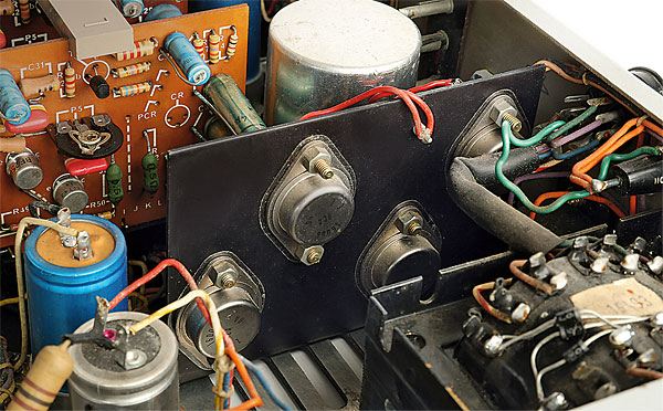
RCA 2N3055 output transistors [centre of image] inside Leak’s Stereo 30 Plus amplifier
Most amplifiers have a ‘mid point’ connection between the two output transistors from where the output signal is taken. This should be at roughly half the supply voltage in designs with a single power rail and at zero volts for those which run from split supplies. If this is not the case find out why before continuing. Usually a defective transistor or leaky diode is the root cause but other components may have been damaged as a result. If only one channel seems to be affected use the other to take reference readings from, but be careful not to blow that one up as well!
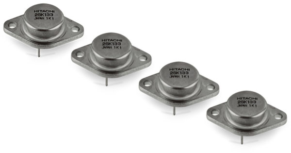
Early MOSFETS are used in the output stage of Hitachi’s HA-7700 power amp
Source or monitor switches that are noisy, dirty protection relay contacts and missing pre/power amp links cause many amplifier malfunctions, so check the simple things like these, first. Many amplifiers have pre-set controls for output stage bias and offset balance. These are fine adjustments that will tend to drift with age and so it is always worth checking that they are correct.
In the absence of the maker’s data the following procedure can be used. With the speakers disconnected, connect a voltmeter across one of the emitter resistors of the output transistors. Adjust the bias control for 10mV, then re-check (and reset if necessary) after ten minutes. After this, adjust the offset for zero volts (or half the rail voltage for single-supply designs) at the midpoint and repeat the process for the other channel. This will be close enough to the maker’s specification for most models to obtain good performance along with reliable operation.
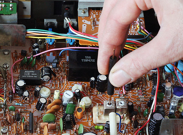
Using an insulated tool to adjust the core of the discriminator coil inside an Hitachi FT-8000 stereo FM tuner to achieve best reception
FM Tuners
These are the most reliable of vintage hi-fi components and most faults tend to be trivial: blown bulbs, broken drive cords, noisy switches and the like. A more complex but common problem is an inability of the tuner to ‘lock’ onto a broadcast, usually with the result that the sound is muted when stereo reception is selected, the stereo decoder doesn’t work or the digital frequency display is incorrect by a small amount, say 0.5MHz. This is often due to the discriminator coil, which forms part of the detector circuit, being in need of adjustment.
First rule: don’t touch anything until you have confirmed which part is the discriminator coil as random twiddling will ruin any tuner. Note the position of anything you touch so that it can be returned to its original setting if the desired results are not obtained. Once identified, buy or make a non-metallic tool with which to adjust the coil’s core.
For tuners with digital displays, tune to a strong local station whose frequency is known to you then set the tuning so the display is correct (even if the sound is then distorted or absent). If possible with the model in hand, next select mono reception and adjust the discriminator coil gently and carefully for the best reception. Half a turn in one direction or the other is normally all that is required. Try some other stations and confirm that they appear at the correct frequency.
When it comes to mechanically tuned models the process is different. Tune to a local station again and turn on the set’s AFC (automatic frequency control) function. Adjust the discriminator for the best sound quality as above, or if the tuner has a balance meter adjust to centre the needle. That is normally all that is required.
If the stereo decoder still doesn’t work and it’s a PLL (Phase Locked Loop) type, the 19kHz oscillator may be out of adjustment. This is normally a preset resistor near the chip (PLL types are invariably IC based) and slight adjustment may be required. Never touch the ‘separation’ adjustment as an FM stereo signal generator is required to set that up that correctly.
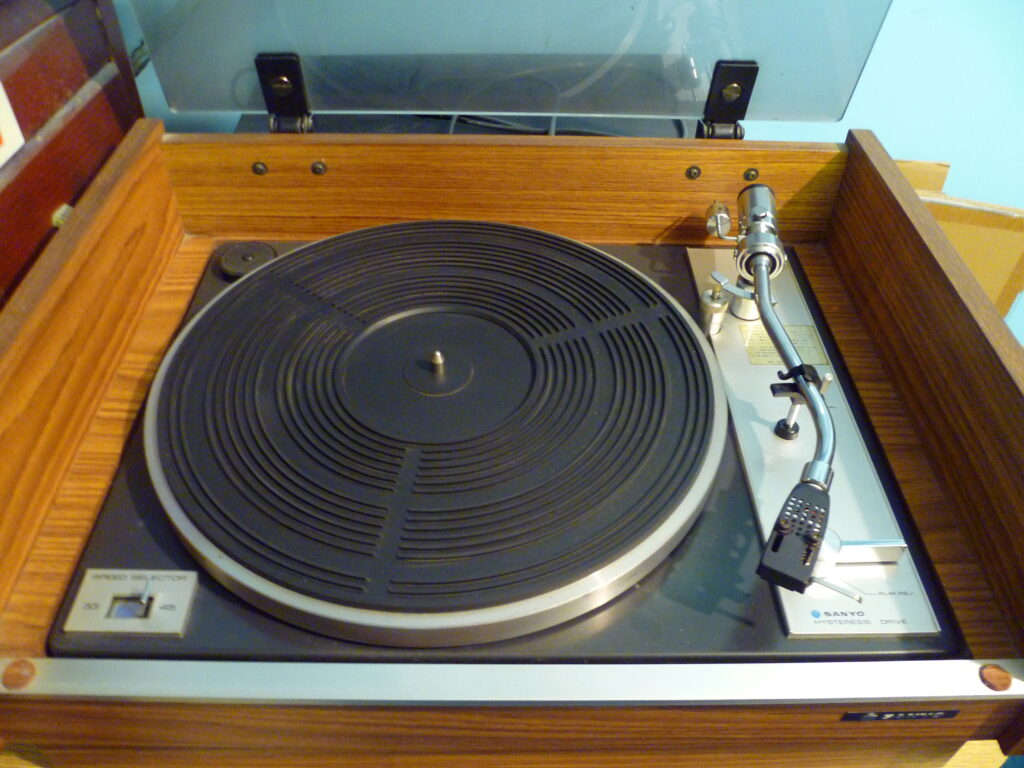
Turntable Troubles
From an electrical point of view, the majority of turntables are simply a motor in a box, faults usually being of a mechanical nature and obvious. Faults in automatic mechanisms are almost always due to hardened lubricants and corrosion, especially where dissimilar metals are in contact. For example, a die-cast alloy lever running on a steel spindle is a typical trouble spot. Indeed, anything that doesn’t move without resistance is suspect.
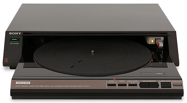
The linear-tracking Sony PS-FL7 [HFN Mar ’20]turntable. The belt that drives the tonearm carriage can stretch with age
Direct-drive turntables contain electronic servo systems which can cause problems. If the motor lacks power, won’t start unaided or sometimes runs in the wrong direction then it is likely that one of the sets of coils in the motor isn’t being driven (there are normally two or three, depending on the design).
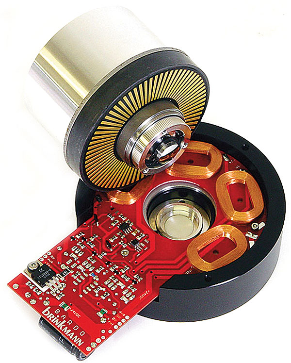
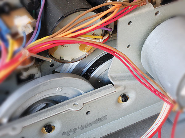
A typical motor from a direct-drive turntable with its sets of coils revealed
The driver transistors for the coils and the hall sensors in the motor are the most likely suspects when this happens. The approach here is to compare measurements taken with the working part of the motor because this should quickly reveal what is amiss.
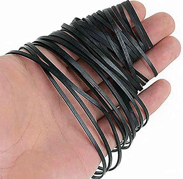
Linear tracking adds another level of complexity to a turntable, but on the whole these systems have proved reliable over time. The most troublesome component is the little belt which links the motor to the rest of the mechanism. Its tension is critical. If it’s too loose it will slip, while if it’s too tight the deck’s tracking servo won’t work properly.
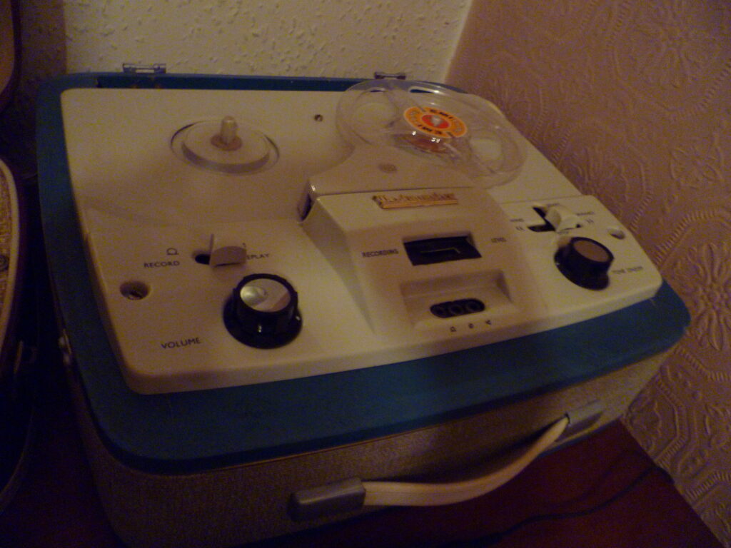
Cassette Decks
Most cassette deck repairs involve belts so try to get a set on hand before starting work. Often the belts will have dissolved into a sticky goo which is time-consuming and messy to remove, but methylated spirits or isopropyl alcohol on a rag will help.
A sticky belt inside an Aiwa AD-R450 cassette deck. Replacement belts are readily available online
The most common electronic problem is that one or other channel overloads on playback with a loud hum through the speakers, often after a recording is attempted. This is normally due to dirty contacts in the record/replay switch and a dose of contact cleaner often cures it. Some decks have a relay to switch the head connections between record and playback and a similar thing can happen if this is faulty.
To give good performance and interchangeability a cassette deck has to be in a good state of adjustment. The principle is to set up the playback conditions first, then the recording side of things. Adjustments are always made with any noise reduction systems switched off. Use a speed adjustment tape (normally 315Hz, 333Hz or 1kHz) and a frequency counter to set the speed correctly, then an azimuth reference tape to set the head at an exact right angle to the tape edge.
Most decks have a Dolby symbol on their VU meters somewhere (normally just inside the red section). Play a Dolby level test tape and adjust the deck’s playback level controls so that the meters point exactly to this mark. Assuming that the mechanics and the head aren’t dirty or worn the deck will now play a ‘standard’ recording correctly.
Next, record alternately a 1kHz and a 10kHz tone at around –20VU on the meters onto a quality tape. Using either an oscilloscope or an AC RMS voltmeter connected to the deck’s outputs, adjust the recording bias so that both these tones are at the same level on playback – it may take a few attempts to get this right. Less bias will yield a treble lift but will also increase distortion. If the left and right settings end up being radically different, it is probable that the machine’s head is worn out.
Once that is done, record a 1kHz tone at 0VU on the meters and play it back. Adjust the record current controls until the recording plays back at 0VU. Although not as exact a calibration as might be achieved at the factory, this procedure will give results which will be more than good enough for domestic use if the rest of the machine is in good condition.
Compact Disc
In general, CD players are too complex for the beginner and bring the risk of permanent sight damage due to laser exposure. However, lazy tray action due to worn loading belts can be an easy fix, depending on how accessible the belt is. With some players it just drops in on the top, though for others virtually the whole machine needs to come apart.
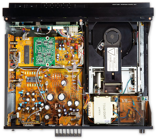
Interior view of Philips CD960 CD player [HFN Jul ’20]. The tray mechanism, which uses belts and motors can give trouble, but replacement kits are available
Loss of the track display can be due to something as simple as the bulb behind an LCD panel failing. For more complex faults, a check on the various switches around the deck and on the presence of the correct voltage on the various supply lines often bears fruit. Not all CD player faults involve unobtainable lasers and intricate digital electronics.
Setting Up a Workshop
A good workshop evolves over time, so assembling one from scratch is a question of setting priorities. Basic hand tools are a must, but don’t waste money on cheap ones. Rather, always buy the best you can afford.
Hi-fi equipment is often assembled with a mixture of Phillips and Pozidrive crosshead screws. They look much the same, but the shape of the cross is slightly different. Use of the correct tool ensures that the screw heads don’t get damaged.
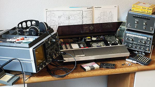
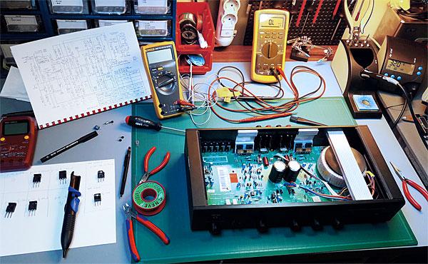
A typical workshop with a Bang & Olufsen Beocord 5000 tape deck from 1984 on the bench. To the right is a Philips PM 6456 FM signal generator and PM 5129 waveform generator
As well as screwdrivers (flat, Phillips, Pozidrive, hex and Torx) you will need some fine pliers, cutters and a set of spanners (combination and box) covering approximately 4mm to 13mm (including 5.5mm, which is a very common size in hi-fi).
Soldering is another important part of repairing electronics. Start by practicing on old scrap boards, not your treasured equipment. Don’t pick an iron which has a tip that is too small because it won’t carry enough heat to the work. A temperature-controlled iron is desirable, the Antex TCS model being a good choice for audio work. This model also has a wide range of tips available for it.
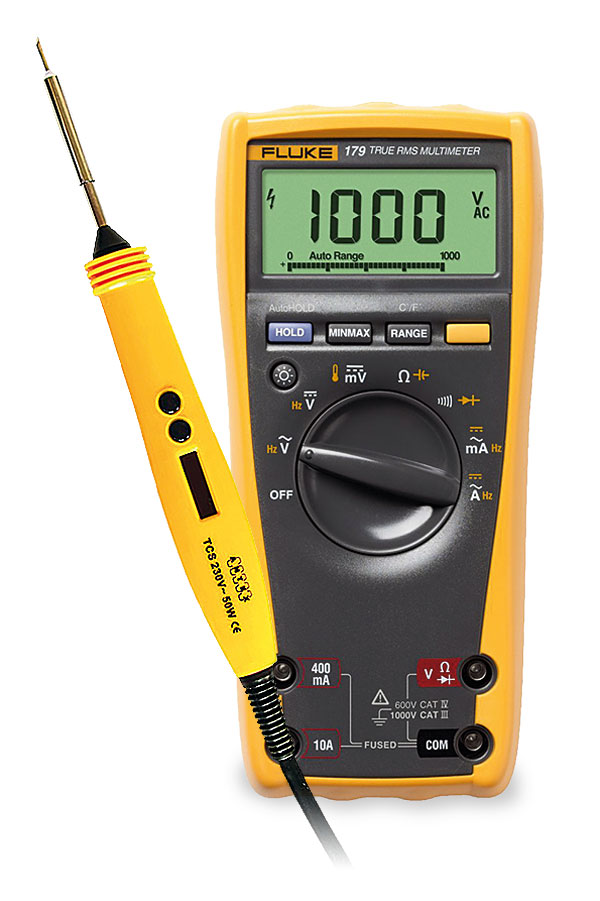
Antex TCS soldering iron and Fluke 179 multimeter
As for test equipment, most novices need just three things: a multimeter, an oscilloscope and a signal or function generator. The most important of these is the meter, modern digital ones combining the functions of what once required a number of separate instruments.
For audio work you will need true RMS (root mean square) reading of AC voltages at least up to 1kHz, resistance measurement up to 10Mohm and the ability to check semiconductor junctions. Useful extras are a capacitance measuring function (1µF to 2000µF) and a frequency counter covering the audio band. The Fluke 179 ‘True-RMS’ multimeter, although not cheap, is ideal.
Of the more exotic test instruments, an audio oscillator (a signal or function generator) is useful when it comes to checking amplifiers and tape recorders. They are expensive if bought new, but can represent good value if acquired secondhand. Here, 10Hz to 100kHz is a basic frequency coverage requirement. If your meter has the ability to measure frequency you can verify the calibration against that.
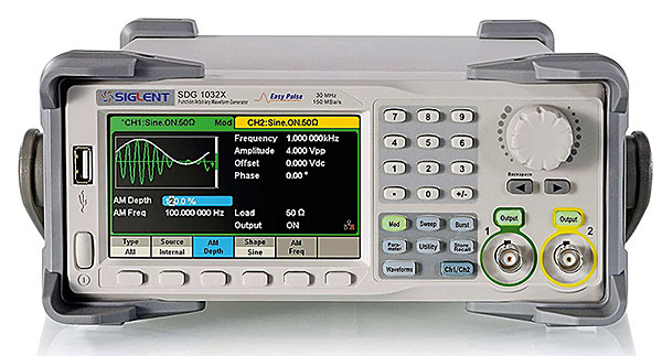
Siglent’s SDG1032X is an affordable signal generator
Higher frequency generators for tuner alignment are needed less often, now that the majority of tuners use ceramic IF filters. An oscilloscope is unlikely to be used much, other than for repairing CD players and tape recorders. A DC-20MHz+ model will cover all the simpler tasks, but for Compact Disc work in particular, 50 or even 100MHz coverage may be required.
With thanks to Tim Jarman of Hi-Fi News for the above information
Vintage Radio, Hi Fi Audio, Repairs And Restoration
Hi, having scrolled down this far, please let me introduce myself.
My name is David Wills and my workshop is based in Bedworth, Warwickshire, England.
If you have an old valve radio, amplifier, record player, tape recorder or any type of portable vintage audio equipment, please feel free to contact me, using the email address below, outlining a brief description of your audio equipment and the nature of the fault, for a free estimate for repair or restoration.
I can visit you at your home to look at your vintage audio item, if you are within a 15 mile radius area of my location, Bedworth.
For anyone further away, you can arrange to visit me with your item, or post the item to me, well packaged, for an estimate.
I specialise in audio equipment from the late 1950’s to the early 1990’s.
Be it valve or transistor equipment, I can give you an evaluation for a basic repair ‘to get it working’, or for a full restoration to bring it back to full working order and cosmetic condition.
Please note, I do not have the facilities to accommodate large radiograms or stereograms and likewise I do not look at digital radios or anything to do with modern up to date technology.
So in the main, as mentioned above, it is just valve radios or top quality vintage transistor radios, portable record players or quality record decks, tape recorders, vintage amplifiers or amplifier/tuners. I can also look at vintage guitar amplifiers.
I look forward to hearing from you.
Bringing New Life to Classic Audio Equipment
Vintage Audio Repairs, Bedworth, Warwickshire, England.
Information On The Repair And Restoration Of Vintage Audio Equipment.
For a FREE estimate on the repair, servicing and restoration of your vintage audio equipment, please email me at audiorepairuk@aol.com